|
|
Post by keurslagerkurt on Jan 18, 2021 22:38:12 GMT
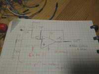
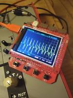
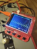
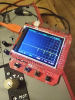
Hi all! So today finally my MCP602 chips arrived, and I'm having a lot of fun already. I found a video (link below) on youtube, explaining an obscure 'deliberate misusage' of opamps (one could call it abused electronics  ), derived from some old Buchla schematics. The original circuit acts like some weird 'gate' on the oscillators, breaking up the sound by setting every voltage below a certain treshold equal to ground (the so-called 'deadband'). Further below i also have some sound demo's and scope pictures. ![]()  The circuit is dead simple, so I tried to set it up (drawing of final circuit below). I realised I need the 'ground' at the + of the opamp to be the center of our waveform, so I set up a virtual ground of 2.5V. I changed Rf to a potentiometer of 100K, giving me control over the 'amount of deadband'. I also added the second MCP opamp as an output buffer (as I had huge voltage drops due to getting a high output impedance with the pot). I tried to center the incoming audio around 2.5V by adding a capacitor of 10uF and a resistor of 1M to virtual ground (2.5V). I'm not sure if this 'hurts' the input audio or not? I just made a bet with the values, and I'm not sure how well its centered, but it seems like it helped the sound.  So I'm still searching for some answers (or inspiration!): - I tried adding an LFO at the 2.5V 'virtual ground), and it sounded cool, but a little too untamed even with attenuation. I think I should make sure the LFO is centered around 2.5V, but how would I do that? Adding a cap removes the possibility of a slow LFO i think? - I use the pot as a simple resistor (only two legs), would it work for CV if I just place a vactrol in parallel? - do I need extra considerations for interfacing etc, or is the input cap & output buffer enough? Here is a sound demo link on soundcloud: soundcloud.com/zzzvm/kurtsdeadband-demo/s-KyH9szKgZmWI especially like the effect on rich noises, like some weird breaking up semi-highpass filter. Its also really nice on white noise I think, it makes it very tame in a comforting way (i have a soft spot for synth campfires). Below are some scope pictures while i turn up the effect on the same waveform     youtube source (great channel!): Kurt out! |
|
namke
wonkystuff
electronics and sound, what's not to like?!
Posts: 686
|
Post by namke on Jan 19, 2021 8:20:49 GMT
This looks like one of the ‘wavefolder cells’ in the Buchla 259 (I’ve been looking at these a little recently)  This paper does some analysis for the purposes of virtual modelling, but the circuit is introduced early on… www.dafx17.eca.ed.ac.uk/papers/DAFx17_paper_82.pdf |
|
|
|
Post by robertlanger on Jan 19, 2021 8:22:00 GMT
Interesting! For the LFO modulation, I'd recommend a dedicated adder OpAmp that provides the basic 2.5 volts without LFO and adds the additional modulations. Could be a simple inverting adder, + of the OpAmp to a (fixed) virtual ground (2 resistors) and 2...n resistors to the summing point (- of OpAmp). One of the resistors is fed by the fixed 2.5 volts, the LFO could go through an attenuator pot to it's summing resistor. One end of the pot not to real ground, but also to 2.5 virtual ground.
I hope it's clear? I have no schematics editor at hand ;-)
|
|
namke
wonkystuff
electronics and sound, what's not to like?!
Posts: 686
|
Post by namke on Jan 19, 2021 9:07:48 GMT
This looks like one of the ‘wavefolder cells’ in the Buchla 259 (I’ve been looking at these a little recently)  This paper does some analysis for the purposes of virtual modelling, but the circuit is introduced early on… www.dafx17.eca.ed.ac.uk/papers/DAFx17_paper_82.pdfHeh, I should have watched the video before replying... the 259 is explicitly mentioned at the end (I skipped through to the end). It's interesting to see how this circuit is used in context; subtracting these deadband responses from the original signal is what gives us the wavefolder behaviour... |
|
|
|
Post by keurslagerkurt on Jan 19, 2021 9:11:40 GMT
namke Cool, thanks! Thats also the Buchla module that the video refers to. It's a great video, as it really made me understand the circuit electrically, which makes it a lot more fun to experiment around for me  I've been tinkering on the circuit, just with the one opamp stage and I was wondering if it would be possible to make a wavefolder out of it. Seems like it is haha! I think its already damn cool and nice sounding with just the single stage as building block, it's more of a 'substractive' building block in that case tho. robertlanger That makes sense, I think I understand what you mean! Good that you mentioned that the attenuation pot needs to be wired to virtual ground too  Another fun 'mod' I tested this morning: hooking up the 'virtual ground' of the + opamp to the center lug of a pot, the pot connected across 5V. This gives you control over the deadband 'position', so you can sweep through the wave and eg 'clip' the bottom or top peaks. Pretty neat! (and fun to watch on the scope!)
|
|
namke
wonkystuff
electronics and sound, what's not to like?!
Posts: 686
|
Post by namke on Jan 19, 2021 12:10:07 GMT
Thinking about this deadband -- the other topology is the Lockhart wavefolder which introduces a deadband by using two transistors configured similarly to a push-pull (class B) amplifier - the deadband in this case could also be called crossover distortion  The obligatory link The obligatory link  |
|
|
|
Post by keurslagerkurt on Jan 19, 2021 13:51:47 GMT
namke damn, seems like a fun, simple build! And fitting the 'abused electronics' vibe  Any idea if the same transistors would be useable in the 0-5V world? (Prob should just test it, but I have some work for my actual job too today haha) Did more testing & building today, and ended up with a build I quite liked. The LFO addition works nice, and it creates fun effects: it wobbles the dead band, so it can effectively work as a weird 'VCA', only letting audio through while the CV is at its peaks (both up and bottom). You can off-center it with a pot, which actually gives the rhythmical pulses a swing effect! Its also good for evolving the sound. I also tried the 'bandwith' pot with a vactrol in parallel for CV, but it was very hard to tweak, it was kinda 'on or off', making it not very interesting. This is the circuit i ended up with, i felt fancy so i drew it out and acted like it's a "official very very real design". Tested a lot of different pot values & gain values. It uses only readily available parts: 2 x MCP602s, some 10k, 15k & 1M resistors and three pots: 50k, 250k and 500k. Oh and also one 10 uF cap. I think you can build it with just the Braedboard kit even, swapping the 15k's for 10k and just leaving the cap out. You'd only need a 500k pot (smaller pots are usuable, but you'll be mainly stuck in the 'very distorted' sound region). Should I also put a 10uF at the output together with a 1M resistor to 2.5V? I don't know if thats best practice, but as is, the build works without it.  I have one spare MCP opamp, maybe could be nice to just make an extra buffer patchable on the board? I think I'll try fitting this on a 1 width protoboard build, I'll record some sound demos once its finished!
|
|
|
|
Post by keurslagerkurt on Jan 19, 2021 13:56:54 GMT
Forgot one resistor on the schematic above: right beneath the 10uF cap at the input, there should be one 1M resistor going to 2.5V.
|
|
|
|
Post by keurslagerkurt on Jan 31, 2021 16:36:57 GMT
Update: So I now have a working 'prototype' that fits in 1U (demo here)!  So thought I'd update this thread for future reference. I did end up using other pot values: 100K for the band 'width' control, 100K for the 'center' pot control. I also lowered the 15k resistor behind the 'width' opamp to 1k. I'm not sure why the behavior was so different on my protoboard, as thats why I changed the values. The new values came closest to the behavior originally on my breadboard. Probably the original pots (from aliexpress) where just off, or maybe the different mcp chips (also aliexpress) had different characteristics.. As you see, I didnt use any 'quality' components, so that might have been the problem. I really have no clue! There will of course be some more improvements for the next prototype (hopefully on pcb!): - Remove the input cap and use a switch to alter the buffer bias between 0 or 2.5V, so both CV and Audio can be manipulated. - Tweak the pot values for a stable result - Make the output non-inverting (changing the buffer/gain stage). This was no problem for audio, but it would be usefull for CV ofc. - Finding a use for the last MCP free op-amp without making the circuit a lot more complicated. Something I was thinking but that might be too complicated: adding a second 'deadband' opamp in parallel to the first. But this one uses the other input for its 'dead band center' bias, so its deadband is located at the inversion (not sure if this is a right assumption!). But i think it would be cool to have a 'symmetrical' option in which there are two bands moving at both sides of the wave. Might be something for a bigger version tho! So now i'll go off and try learn some pcb design basics! x Kurt |
|
|
|
Post by keurslagerkurt on Feb 26, 2021 16:21:35 GMT
Bumping the updated schematic in this thread if any of the DIY-ers want to play with it. Its at the bottom of this post. Its my second revision with some new features: - a switch to set your 'dead band' horizontal or vertical. - a gain knob to set your output level (as the effect attenuates the input signal to some degree, this offsets that again. It can also be used to 'calibrate' DC inputs so they start at 0V) - 4 audio inputs that get mixed (Mixer unit B input style) - 4 CV inputs that get mixed - CV mix output (raw, buffered output from the CV mix = CV ins + offset CV) The vertical mode was a suprise when I tried to swap the deadband opamp terminals in simulation software. Not why I expected, but I think its a really cool extra feature, especially for CV manipulation! Picture below with the input LFO to the left, output to the right.  Here is the PDF with the full circuit as is (untested yet in real life however). I also added a falstad simulator txt file below with the raw circuit if you'd like to play around with it. Cya! |
|
 ), derived from some old Buchla schematics. The original circuit acts like some weird 'gate' on the oscillators, breaking up the sound by setting every voltage below a certain treshold equal to ground (the so-called 'deadband'). Further below i also have some sound demo's and scope pictures.
![]()


 ), derived from some old Buchla schematics. The original circuit acts like some weird 'gate' on the oscillators, breaking up the sound by setting every voltage below a certain treshold equal to ground (the so-called 'deadband'). Further below i also have some sound demo's and scope pictures.


 I've been tinkering on the circuit, just with the one opamp stage and I was wondering if it would be possible to make a wavefolder out of it. Seems like it is haha! I think its already damn cool and nice sounding with just the single stage as building block, it's more of a 'substractive' building block in that case tho.

